EMF Equation of Synchronous Generator or Alternator:
We know that Synchronous Generator or Alternator will generate an EMF. The following is the derivation of emf equation of Synchronous Generator or Alternator.
Let Φ = Flux per pole, in Wb
P = Number of poles
N = Synchronous speed in r.p.m
f = Frequency of induced emf in Hz
Z = Total number of conductors
Zph = Conductors per phase connected in series
Zph = Z/3 as number of phases = 3
Consider a single conductor placed in a slot.
The average value of emf induced in a conductor = dΦ/dt
For one revolution of a conductor,
eavg per conductor = (Flux cut in one revolution/Time taken for one revolution)
Total flux cut in one revolution is Φ x P.
Must Read:
Time taken for one revolution is 60/Ns seconds.
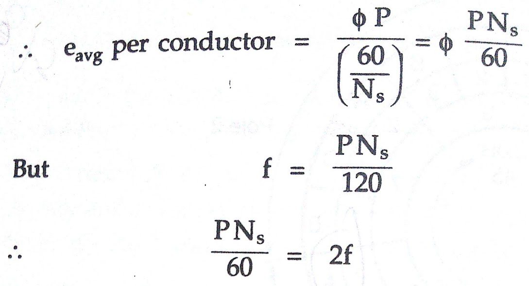
Substituting in above equation
eavg per conductor = 2 f Φ volts
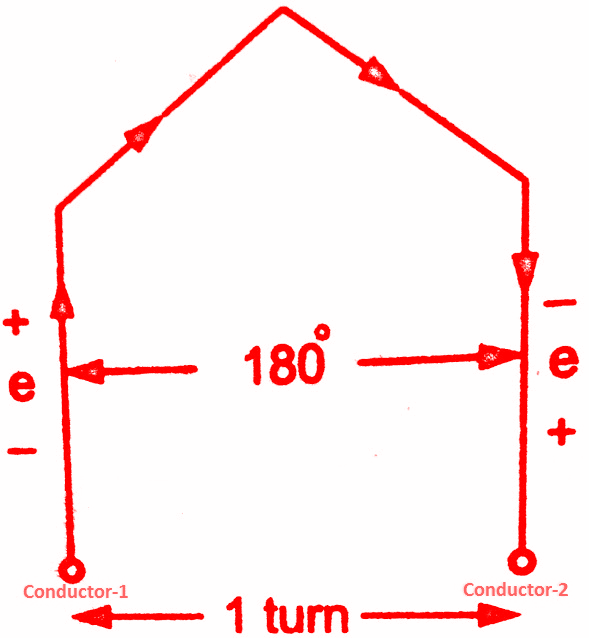
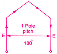
Assume full pitch winding for simplicity i.e. this conductor is connected to a conductor which is 180° electrical apart. So these two emf’s will try to set up a current in the same direction i.e. the two emf are helping each other and hence resultant emf per turn will be twice the emf induced in a conductor.
emf per turn = 2 x (emf per conductor) = 2 x (2 f Φ)
= 4 f Φ volts.
 |
| Turn of full pitch coil |
Let Tph be the total number of turns per phase connected in series. Assuming concentrated winding, we can say that a are placed in single slot per pole per phase (So induced emf’s in all turns will be in phase as placed in a single slot. Hence net emf per phase will be algebraic sum of the emf’s per turn.
Average Eph = Tph x (Average emf per turn)
Average Eph = Tph x 4 f Φ
This textbook “Electrical Machinery by P.S. Bhimbhra” is the best in industry. Grab it now for very less price.

But in ac circuits, RMS value of an alternating quantity is used for the analysis. The form factor is 1.11 of sinusoidal emf.
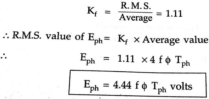
Key point: This is the general emf equation for an induced emf per phase for full pitch, concentrated type of winding.
where Tph = Number of turns per phase
Tph = Zph/2 —>As 2 conductors constitute 1 turn
But as mentioned earlier, the winding used for the alternators is distributed and short pitch hence emf induced slightly gets affected. Let us see how the effect of distributed and short pitch type of winding on the emf equation of Synchronous Generator or Alternator. The below are the effects which make slight changes in the emf equation of synchronous generator or alternator derivation.
Pitch Factor or Coil Span Factor (Kc):
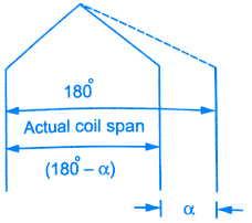
In practice, short pitch coils are preferred. So coil is formed by connecting one coil side to another which is less than one pole pitch away. So actual coil span is less than 180°. The coil is generally shorted by one or two slots.
Key Point: The angle by which coils are short pitched is called angle of short pitch denoted as ‘α‘.
α = Angle by which coils are short pitched.
 |
| Angle of short p |
As coils are shorted in terms of the number of slots i.e. either by one slot, two slots and so on and slot angle is β then the angle of short pitch is always a multiple of the slot angle β.
α = β x Number of slots by which coils are short pitched
or α = (180° – Actual coil span of the coils)
 This is shown on the left side figure. Now let E be the induced emf in each coil side. If the coil is full pitch coil, the induced emf in each coil side help each other. Coil connections are such that both will try to set up a current in the same direction in the external circuit. Hence the resultant emf across a coil will be algebraic sum of the two.
ER = E+ E = 2E
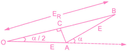
Now the coil is short pitched by angle α, the two emf in two coil sides r longer remains in phase from external, circuit point of view. Hence the resultant emf is also no longer remains the algebraic sum of the two but becomes a phasor sum of the two as shown in the figure to the left. Obviously, ER in such a case will be less than what it is in case of full pitch coil.
From the geometry of the above figure, we can write,
AC is perpendicular drawn on OB bisecting OB.
1(OC) = l(CB) = ER/2
and ∠BOA = α/2
cos(α/2) = OC/OA = ER/2E
ER = 2Ecos(α/2)
This is the resultant emf in case of a short pitch coil which depends on the angle of short pitch ‘α‘.
Key Point: Now the factor by which, induced emf gets reduced due to short pitching called pitch factor or coil span factor denoted by Kc.
It is defined as the ratio of resultant emf when the coil is short pitch to the result emf when the coil is full pitched. It is always less than one.
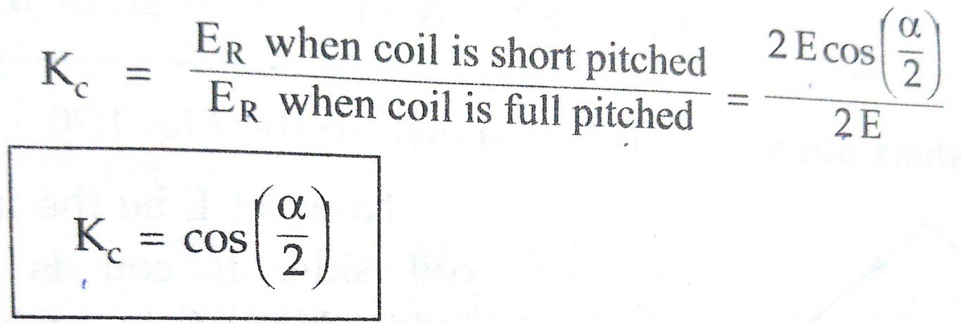
where α = Angle of short pitch
Distribution Factor (Kd):
Similar to full pitch coils, concentrated winding is also rare in practice. Attempt made to use all the slots available under a pole for the winding which makes the nature of the induced emf more sinusoidal. Such a winding is called distributed winding.
Consider 18 slots 2 pole alternator. So slots per pole i.e. n = 9.
m = Slots per pole per phase = 3
β = 180°/9 = 20°
Let E = Induced emf per coil and there are 3 coils per phase.
In concentrated type, all the coil sides will be placed in one slot under a pole. So induce’ e,m.f. in all the’ coils will achieve maxima and minima at the same time i.e. all of them will be in phase. Hence resultant emf after connecting coils in series will be algebraic sum of all the emf’s as all are in phase.
As against this, in distributed type, coil sides will be distributed, one each in the 3 slots per phase available under a pole as shown in the below figure.
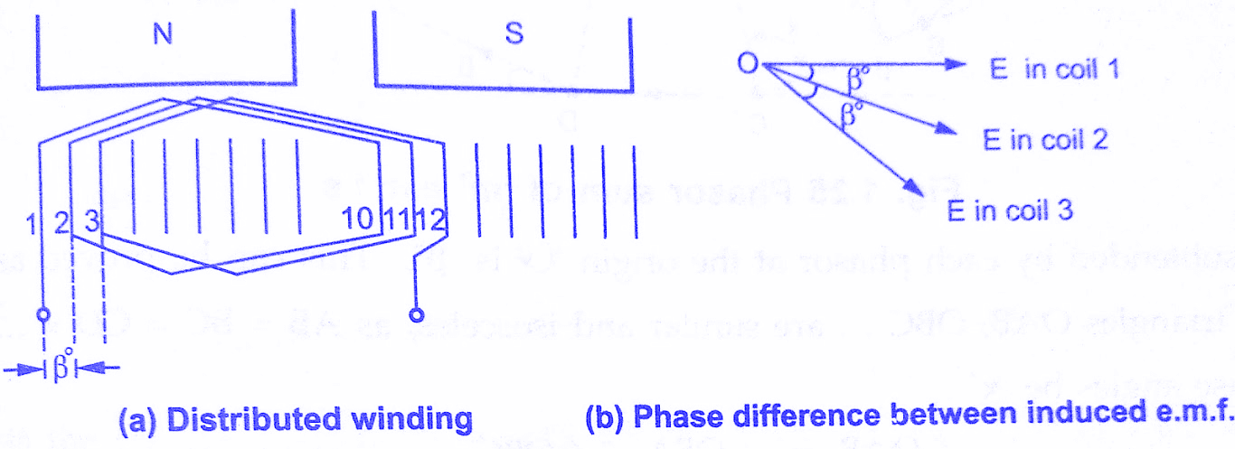
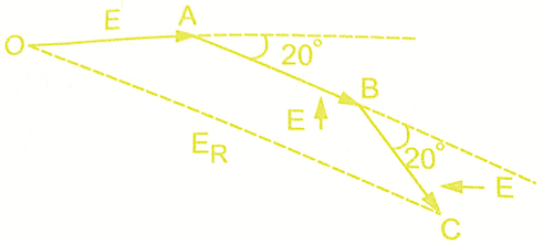
Though the magnitude of emf in each coil will be same as ‘E’, as each slot contributes phase difference of β° i.e. 20° in this case, there will exist a phase difference of β° with respect to each other as shown in the above figure(b). Hence resultant emf will be phasor sum of all of them as shown in the figure to the left side. So due to distributed winding resultant emf decreases.
Key Point: The factor by which there is a reduction in the e.mf. due to the distribution of coils is called distribution factor denoted as Kd.
This textbook “Electrical Machinery by P.S. Bhimbhra” is the best in industry. Grab it now for very less price.
Let us see the derivation for its expression.
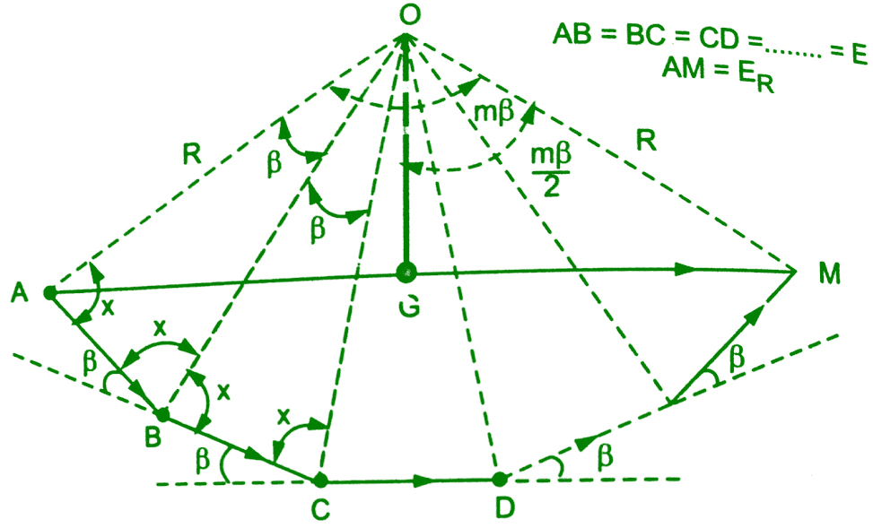
In general, let there be ‘n’ slots per pole and ‘m’ slots per pole per phase. So there will be ‘m’ coils distributed under a pole per phase, connected in series. Let E be the induced emf per coil. Then all the ‘m’ emf’s induced in the coils will have successive phase angle difference of β=80°/n.While finding out the phasor sum of all of them, phasor diagram will approach a shape of a ‘m’ equal sided polygon circumscribed by a semicircle of radius ‘R’.This is shown in the below figure AB, BC, CD etc., represent emf per coil. All the ends are joined at ‘O’ which is the centre of the circumscribing semicircle of radius ‘R’.
 |
| Phasor sum of ‘m’ emf’s |
The angle subtended by each phasor at the origin ‘O’ is β°. This can be proved below. All the triangles OAB, OBC… are similar and isosceles, as AB=BC=CD=…..=E.
Let the base angles be ‘x’.
∠OAB = ∠OBA = ∠OBC =…………..=x
and ∠AOB = ∠BOC =……=y (say)
Now in △OAB , 2x + y = 180°
while ∠OBA + ∠OBC + β = 180°
2x + β = 180°
Comparing above two equations, y = β
So ∠AOB = ∠BOC =∠COD =………..= β
If ‘M’ is the last point of the last phasor,
∠AOM = m × β = mβ
and AM = ER = Resultant of all the emfs
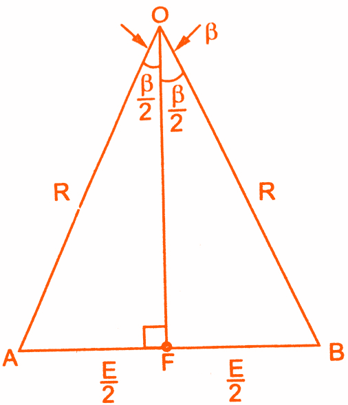
Consider an △OAB separately as shown in the figure to the left. Let OF be the perpendicular drawn on AB bisecting angle at apex ‘O’ as β/2.
l(AB) = E
l(AF) = E/2
and l(OA) = R
Sin(β/2) = AF/OA = (E/2)/R
E = 2R Sin(β/2)
Now consider △OAM, and OG is the perpendicular drawn from ‘O’ on its base bisecting ∠OAM.
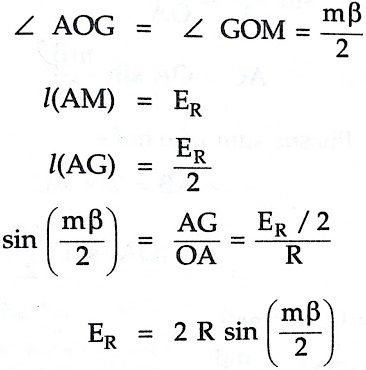
This is the resultant emf when coils are distributed. If all ‘m’ coils are connected, all would have been in phase giving ER as the algebraic sum of all the emf’s.
ER = m × E
we have E = 2R Sin(β/2)
ER = 2mR Sin(β/2)
This is resultant emf when coils are connected.
The distribution factor is defined as the ratio of the resultant emf when coils are distributed to the resultant emf when coils are concentrated. It is always less than one.
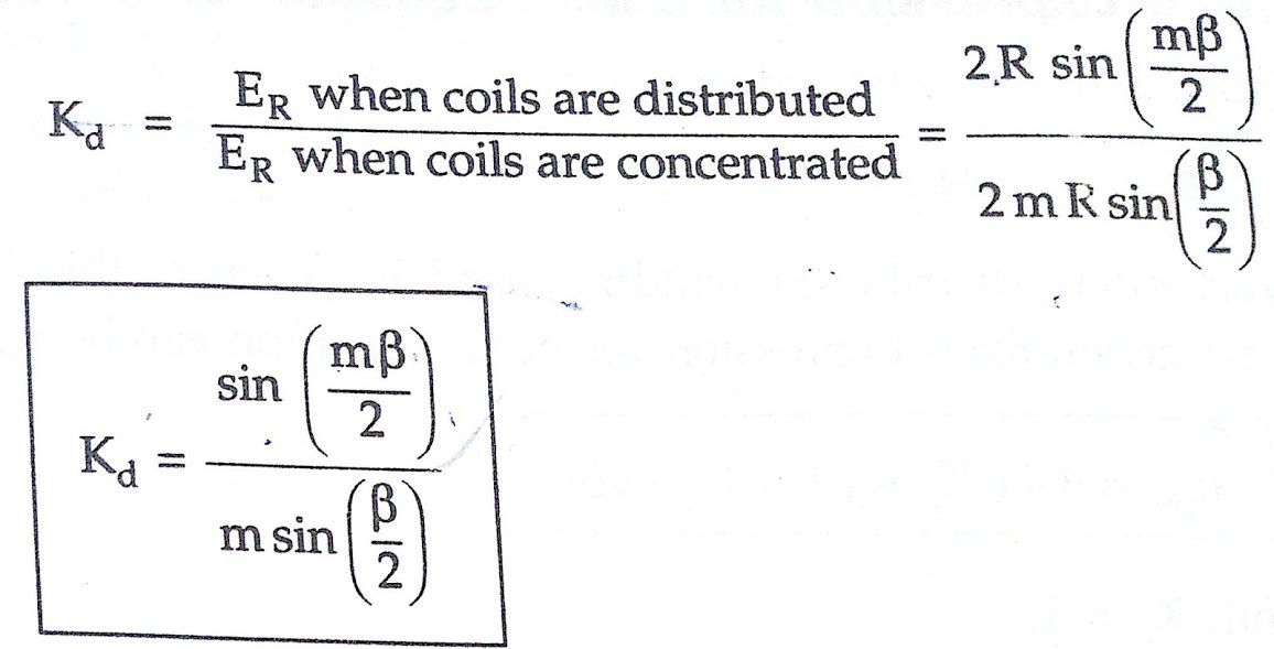
where m = Slots per pole per phase
β = Slot angle = 180°/n
n = Slots per pole
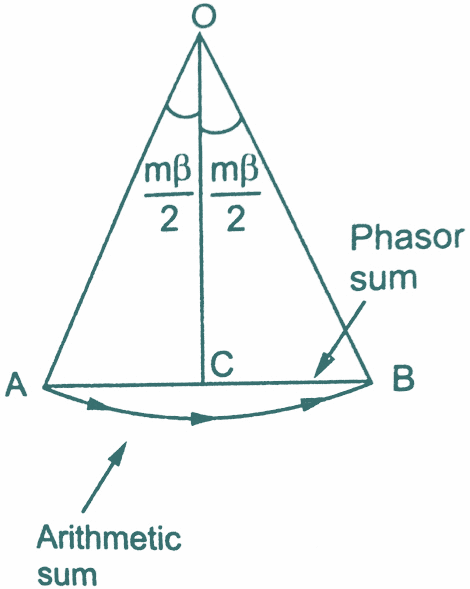
When β is very small and m is large then the total phase spread is mβ. The phasor sum of coil emf’s now become the chord AB of a circle as shown in the figure to the left.
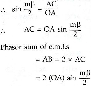
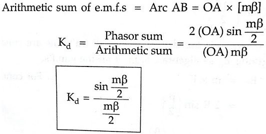
Keypoint: The angle (mβ/2) in the denominator must be in radians.
NOTE: The above formula is used to calculate distribution factor when phase spread is mβ and the winding is uniformly distributed.
Generalised expression for EMF equation of an Alternator:
Considering full pitch, concentrated winding,
Eph = 4.44 f ΦTph volts
But due to short pitch, distributed winding used in practice, this Eph will reduce factors Kc and Kd. So generalised expression for the derivation of emf equation of Synchronous generator or Alternator can be written as
Eph = 4.44 Kc Kd f ΦTph volts
For full pitch coil, Kc = 1
For concentrated winding Kd = 1
Key Point: For short pitch and distributed winding Kc and Kd are always less than unity.
Must Read:
Conclusion:
Now here we have known how derivation of armature emf equation of Synchronous Generator or Alternator is obtained. You can download this post as pdf, ppt.
Comment below for any Queries.