D.C. Generator Characteristics:
The following are the three most important characteristics of a d.c. generator:
1. Open Circuit Characteristic (O.C.C.):
This curve shows the relation between the generated e.m.f. at no-load (E0) and the field current (If) at constant speed. It is also known as magnetic characteristic or no-load saturation curve. Its shape is practically the same for all generators whether separately or self-excited.The data for O.C.C. curve are obtained experimentally by operating the generator at no load and constant speed and recording the change in terminal voltage as the field current is varied.
2. Internal or Total characteristic (E/Ia):
This curve shows the relation between the generated e.m.f. on load (E) and the armature current (Ia). The e.m.f. E is less than E0 due to the demagnetizing effect of armature reaction. Therefore, this curve will lie below the open circuit characteristic (O.C.C.). The internal characteristic is of interest chiefly to the designer. It cannot be obtained directly by experiment. It is because a voltmeter cannot read the e.m.f. generated on load due to the voltage drop in armature resistance.The internal characteristic can be obtained from external characteristic if winding resistances are known because armature reaction effect is included in both characteristics.
3. External characteristic (V/IL):
This curve shows the relation between the terminal voltage (V) and load current (IL). The terminal voltage V will be less than E due to voltage drop in the armature circuit. Therefore, this curve will lie below the internal characteristic. This characteristic is very important in determining the suitability of a generator for a given purpose. It can be obtained by making simultaneous measurements of terminal voltage and load current (with voltmeter and ammeter) of a loaded generator.
Characteristics of Series Generator:
Fig. (3.7) (ii) shows the characteristics of a series wound generator. Since there is only one current (that which flows through the whole machine), the load current is the same as the exciting current.
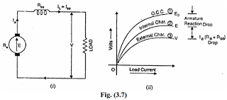
(i) O.C.C.
Curve 1 shows the open circuit characteristic (O.C.C.) of a series generator. It
can be obtained experimentally by disconnecting the field winding from the
machine and exciting it from a separate d.c. source as discussed earlier.
(ii) Internal characteristic
Curve 2 shows the total or internal characteristic of a series generator. It gives the relation between the generated e.m.f. E. on load and armature current. Due to armature reaction, the flux in the machine will be less than the flux at no load. Hence, e.m.f. E generated under load conditions will be less than the e.m.f. E0 generated under no load conditions. Consequently, internal characteristic curve lies below the O.C.C. curve; the difference between them representing the effect of armature reaction [See Fig. 3.7 (ii)].
(iii) External characteristic
Curve 3 shows the external characteristic of a series generator. It gives the
relation between terminal voltage and load current IL:
V = E – Ia(Ra+Rse)
Therefore, external characteristic curve will lie below internal characteristic
curve by an amount equal to ohmic drop [i.e., Ia(Ra + Rse)] in the machine as shown in Fig. (3.7) (ii). The internal and external characteristics of
a d.c. series generator can be plotted from one another as shown in fig. below.
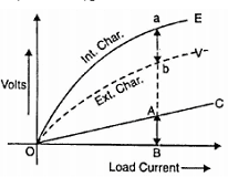
Suppose we are given the internal characteristic of the generator. Let the line OC represent the resistance of the whole machine i.e. Ra + Rse. If the load current is OB, drop in the
machine is AB i.e.
AB = Ohmic drop in the machine = OB(Ra + Rse)
Now raise a perpendicular from point B and mark a point b on this line such that ab = AB. Then point b will lie on the external characteristic of the generator.
Characteristics of a Shunt Generator:
Fig (3.9) (ii) shows the characteristics of a shunt wound generator. The armature current Ia splits up into two parts; a small fraction Ish flowing through shunt field winding while the major part IL goes to the external load.
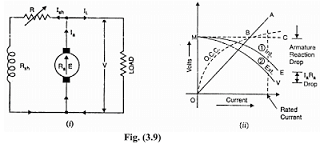
(i) O.C.C
The O.C.C. of a shunt generator is similar in shape to that of a series generator as shown in Fig. (3.9) (ii). The line OA represents the shunt field circuit resistance. When the generator is run at normal speed, it will build up a voltage OM. At no-load, the terminal voltage of the generator will be constant (= OM) represented by the horizontal dotted line MC.
(ii) Internal characteristic
When the generator is loaded, flux per pole is reduced due to armature reaction.Therefore, e.m.f. E generated on load is less than the e.m.f. generated at no load.As a result, the internal characteristic (E/Ia) drops down slightly as shown in Fig.(3.9) (ii).
(iii) External characteristic
Curve 2 shows the external characteristic of a shunt generator. It gives the
relation between terminal voltage V and load current IL.
V = E -Ia Ra =E – (IL + Ish) Ra
Therefore, external characteristic curve will lie below the internal characteristic
curve by an amount equal to drop in the armature circuit [i.e., (IL + Ish)Ra] as shown in Fig. (3.9) (ii).
Note: It may be seen from the external characteristic that change in terminal
voltage from no-load to full load is small. The terminal voltage can always be
maintained constant by adjusting the field rheostat R automatically.