Silicon Controlled Rectifier (SCR):
Silicon controlled rectifier(SCR) is a three-terminal semiconductor switching device which is probably the most important circuit element after the diode and the transistor.Invented in 1957, an SCR can be used as a controlled switch to perform various functions such as rectification, inversion, and regulation of power flow.The SCR has assumed paramount importance in electronics because it can be produced in versions to handle currents up to several thousand amperes and voltages up to more than 1 kV.
The SCR has appeared in the market under different names such as thyristor, thyrode transistor.It is a unidirectional power switch and is being extensively used in switching d.c. and a.c., rectifying a.c. to give controlled d.c. output, converting d.c. into a.c. etc. In this chapter, we shall examine the various characteristics of silicon controlled rectifiers and their increasing applications in power electronics.
A silicon controlled rectifier is a semiconductor device that acts as a true electronic switch.It can (figure below) change alternating current into direct current and at the same time can control the amount of power fed to the load. Thus SCR combines the features of a rectifier and a transistor.
Silicon Controlled Rectifier (SCR) Construction:
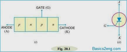
When a PN junction is added to a junction transistor, the resulting three PN junction device is called a silicon controlled rectifier.The above figure(i) shows the construction of Silicon Controlled Rectifier.It is clear that it is essentially an ordinary rectifier (PN) and a junction transistor (NPN) combined in one unit to form PNPN device.Three terminals are taken; one from the outer p-type material called anode A, second from the outer n-type material called cathode K and the third from the base of transistor section and is called gate G.
In the normal operating conditions of SCR, anode is held at high positive potential w.r.t. cathode and gate at small positive potential w.r.t. cathode.The above figure(ii) shows the symbol of SCR.The silicon controlled rectifier is a solid state equivalent of thyratron. The gate, anode and cathode of SCR correspond to the grid, plate and cathode of thyratron. For this reason, SCR is sometimes called thyristor.
Silicon Controlled Rectifier (SCR) Working:
In a silicon controlled rectifier, the load is connected in series with anode.The anode is always kept at positive potential w.r.t. cathode.The working of SCR can be studied under the following two heads:
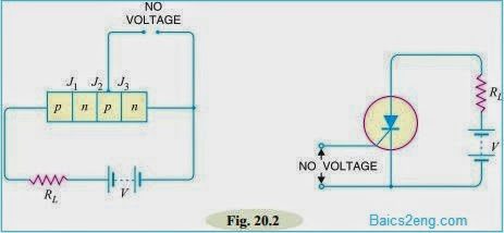
(i) When gate is open: The below figure shows the SCR circuit with gate open i.e. no voltage applied to the gate. Under this condition, junction J2 is reverse biased while junctions J1 and J3 are forward biased.Hence, the situation in the junctions J1 and J3 is just as in an NPN transistor with base open.Consequently, no current flows through the load RL and the SCR is cut off.However, if the applied voltage is gradually increased, a stage is reached when reverse biased junction J2 breaks down.The SCR now conducts heavily and is said to be in the ON state.The applied voltage at which SCR conducts heavily without gate voltage is called breakover voltage.
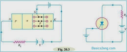
(ii) When gate is positive w.r.t. cathode: The SCR can be made to conduct heavily at smaller applied voltage by applying a small positive potential to the gate as shown in the below figure.Now, junction J3 is forward biased and junction J2 is reverse biased.The electrons from n-type material start moving across junction J3 towards left whereas holes from p-type towards the right.Consequently, the electrons from junction J3 are attracted across junction J2 and gate current starts flowing.
As soon as the gate current flows, anode current increases.The increased anode current, in turn, makes more electrons available at junction J2.This process continues and in an extremely small time, junction J2 breaks down and the SCR starts conducting heavily.Once SCR starts conducting, the gate loses all control.Even if gate voltage is removed, the anode current does not decrease at all.The only way to stop conduction (i.e. bring SCR in off condition) is to reduce the applied voltage to zero.
Conclusion: The following conclusions are drawn from the working of SCR :
(i) An SCR has two states i.e. either it does not conduct or it conducts heavily.There is no state in between.Therefore, SCR behaves like a switch.
(ii)There are two ways to turn on the SCR.The first method is to keep the gate open and make the supply voltage equal to the breakover voltage.The second method is to operate SCR with supply voltage less than breakover voltage and then turn it on by means of a small voltage (typically 1.5 V,30 mA) applied to the gate.
(iii)Applying small positive voltage to the gate is the normal way to close an SCR because the breakover voltage is usually much greater than supply voltage.
(iv) To open the SCR (i.e. to make it non-conducting ), reduce the supply voltage to zero.
Silicon Controlled Rectifier (SCR) Equivalent Circuit:
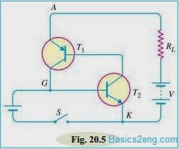
The SCR is shown in the below figure(i) can be visualised as separated into two transistors as shown in the below figure(ii).
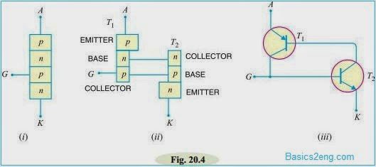
Thus, the equivalent circuit of SCR is composed of pnp transistor and NPN transistor connected as shown in Fig. 20.4. (iii).It is clear that collector of each transistor is coupled to the base of the other, thereby making a positive feedback loop.The working of SCR can be easily explained from its equivalent circuit.
The below figure shows the equivalent circuit of SCR with supply voltage V and load resistance RL.Assume the supply voltage V is less than breakover voltage as is usually the case.With gate open (i.e. switch S open), there is no base current in transistor T2.Therefore, no current flows in the collector of T2 and hence that of T1.Under such conditions, the SCR is open. However, if switch S is closed, a small gate current will flow through the base of T2 which means its collector current will increase.
The collector current of T2 is the base current of T1.Therefore, collector current of T1 increases.But collector current of T1 is the base current of T2.This action is accumulative since an increase of current in one transistor causes an increase of current in the other transistor.As a result of this action, both transistors are driven to saturation, and heavy current flows through the load RL.Under such conditions, the SCR closes.
Silicon Controlled Rectifier (SCR) V-I Characteristics:
It is the curve between anode-cathode voltage (V) and anode current (I) of an SCR at constant gate current.The below figure shows the V-I characteristics of SCR.
(i) Forward characteristics: When anode is positive w.r.t. cathode, the curve between V and I is called the forward characteristic.In the below figure, OABC is the forward characteristic of SCR at IG = 0.If the supply voltage is increased from zero, a point is reached (point A) when the SCR starts conducting.Under this condition, the voltage across SCR suddenly drops as shown by dotted curve AB and most of the supply voltage appears across the load resistance RL.If proper gate current is made to flow, SCR can close at much smaller supply voltage.
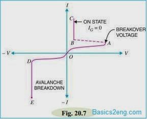
(ii) Reverse characteristics: When anode is negative w.r.t. cathode, the curve between V and I is known as reverse characteristic.The reverse voltage does come across SCR when it is operated with a.c. supply.If the reverse voltage is gradually increased, at first the anode current remains small (i.e.leakage current) and at some reverse voltage, avalanche breakdown occurs and the SCR starts conducting heavily in the reverse direction as shown by the curve DE.This maximum reverse voltage at which SCR starts conducting heavily is known as reverse breakdown voltage.
Thanks for your work on this. I've watched tons of YouTube videos and read tons of websites trying to understand how an SCR works. You brought everything together in a manner I could understand. Your work is appreciated.